Arduino Timer
Arduino Overview
There are many great resources and introductions for getting familiar with an Arduino microcontroller. From http://www.arduino.cc/, the Arduino homepage:
"Arduino is an open-source electronics platform based on easy-to-use hardware and software. It's intended for anyone making interactive projects."
An Arduino (or a microcontroller in general) is a small, simple computer that only does one task. It also provides low level access to digital and analog inputs and outputs. This is perfect for a dedicated timing system.

Arduinos are very affordable. Current prices for an assembled version of the latest revision are about $25 (USD). Any Arduino system should work as an external timing device. This document was written with the Arduino UNO model as a reference.
Installation
This guide assumes you have set up your computer and Arduino so they can talk to one another, and that you understand how to upload new sketches to the Arduino. These topics are well covered in introductory guides like these:
http://arduino.cc/en/Guide/HomePage
http://arduino.cc/en/Tutorial/Blink?from=Tutorial.BlinkingLED
If you prefer working from the command line, I highly recommend Ino as a way to build and upload sketches to the Arduino:
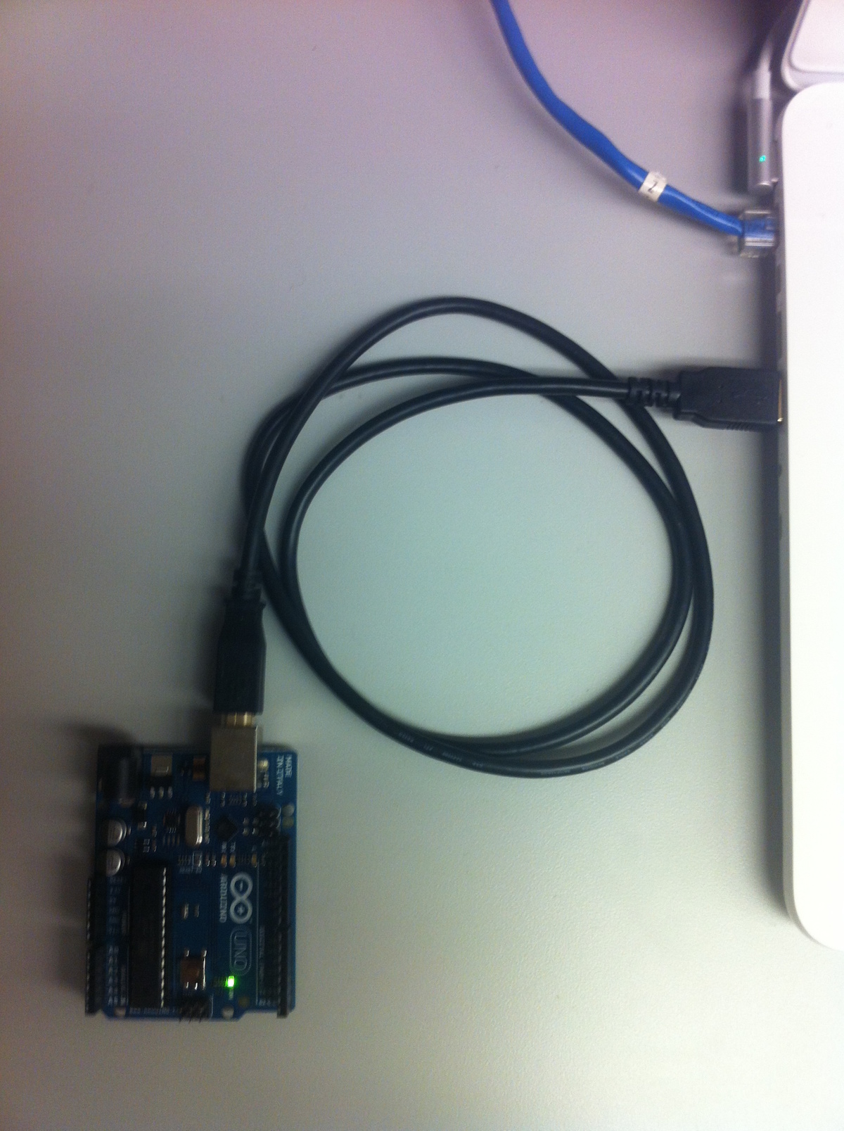
At this point you should have an Arduino connected to your computer via a USB cable. Start by building and uploading the supplied timer sketch. The sketch requires the "SerialCommand" library which is included, but also available here:
http://awtfy.com/2011/05/23/a-minimal-arduino-library-for-processing-serial-commands/
If using the standard Arduino IDE, you will need to import these libraries directly. In the "Arduino" directory (under "Documents" on OS X), place the included external libraries (/lib) in the "libraries" folder.
When you open up your serial monitor (either the one supplied by the Arduino software package via "Tools"->"Serial Monitor", or any other that you have configured), you should see the following::
   lablibduino.0.2
   Ready

If not, please check to make sure there were no errors reported when uploading the sketch to your Arduino.
Configuration
Now it's time to attach something to the Arduino that we can use to create events for the Arduino to detect. Our goal with events is to distill a specific event down to a change in voltage. This gives us a lot of flexibility in the events that we can detect.
An easy one to start with is a stereo audio source. These are available on most computers and a lot of effort has gone in to making them accurate for rendering sounds. Analog audio is sent over cables as an electrical representation of the original; this is what typically drives a speaker to reproduce the sound in the form of audible sound waves.
We can use one channel from the stereo audio signal to trigger a start event and the other channel to trigger a stop event. To connect the audio source to the Arduino, use a cable that connects to the audio source (typically 1/8" stereo connector on many computers), and then strip the wires on the other end of the cable. There should be two wires for each channel: one for the signal and one for the ground.
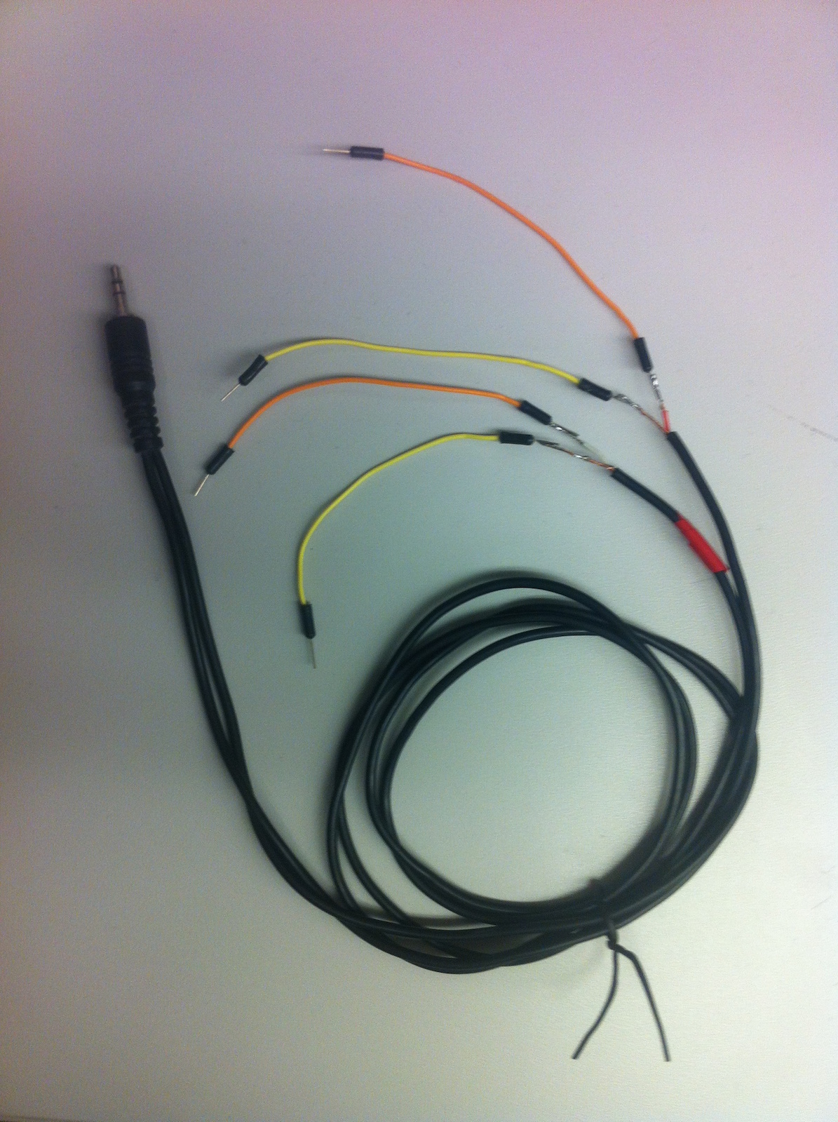
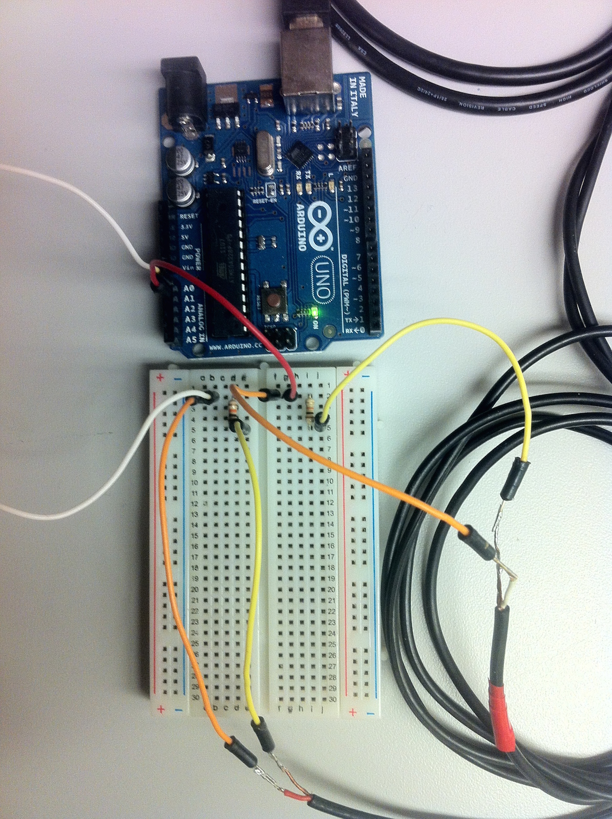
Using a breadboard, insert a 10K resistor between the two wires for a channel, and then connect a wire before the resistor to one of the analog inputs on the Arduino. Repeat this for the other audio channel.
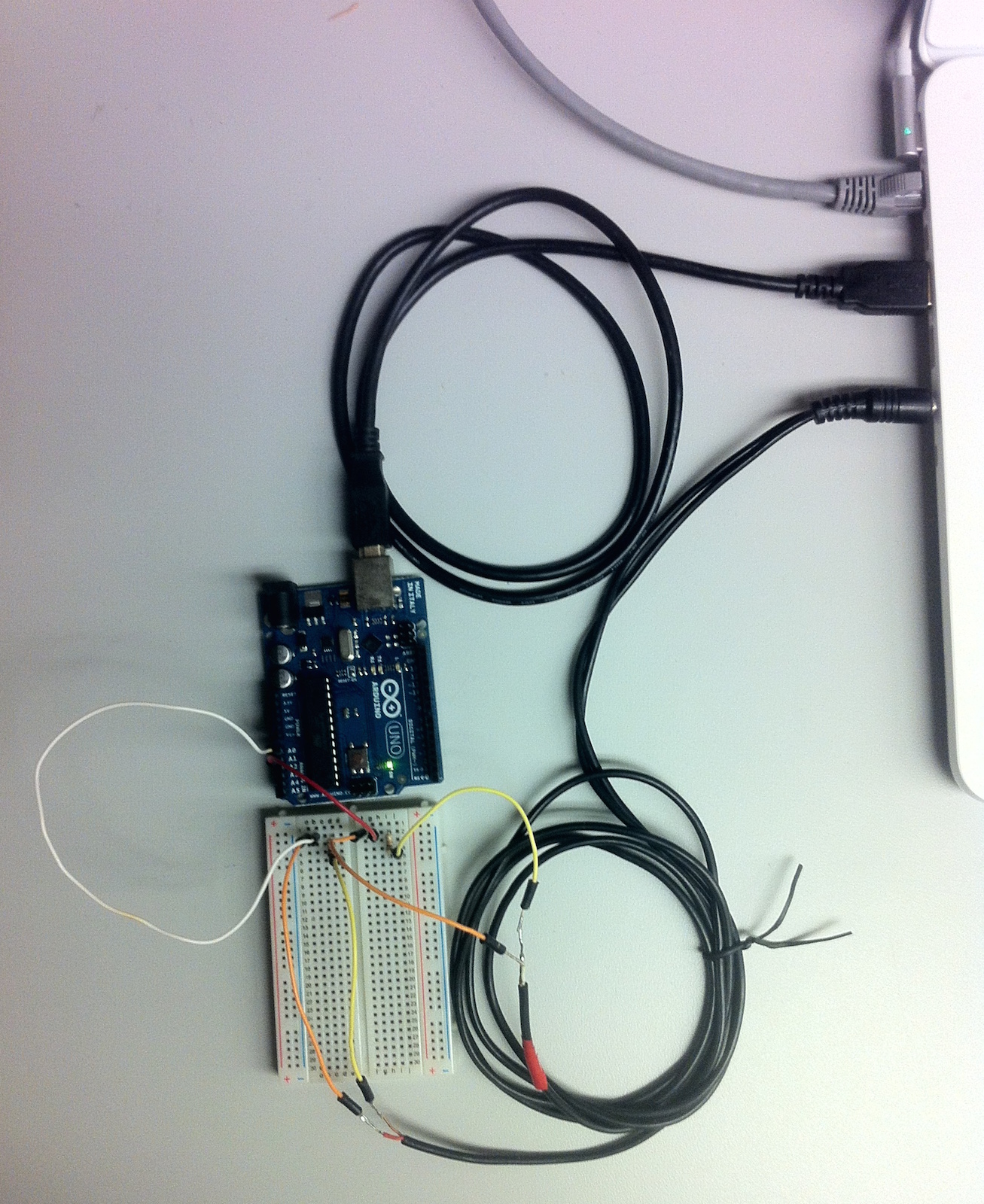
Closer view:
Debug
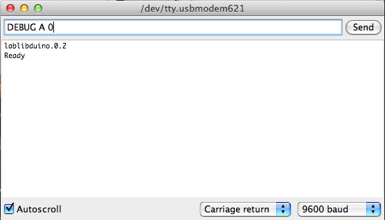
Now that everything is connected it's helpful to check to make sure that values are being read by the Arduino. The above sketch includes a debug mode to help you see what values are showing up. You can enable it by sending the following command via the serial connection::
DEBUG A 0
The first parameter toggles if you want to look at analog or digital pins / inputs. The second parameter determines which pin to look at. Since I plugged one of the audio channel lead wires into port A0 on the Arduino, the second parameter is 0. If you are using the Serial Monitor that comes with the Arduino IDE, be sure to set "Carriage return" as the line return option. Otherwise commands will not be processed by the sketch on the Arduino. For other serial interfaces, you may need to include a '\r' at the end of the command string.
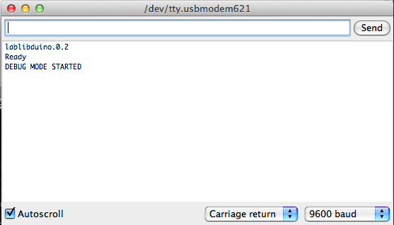
After sending the command (Return, or "Send" button), you should see a message that the debug mode has been started::
DEBUG MODE STARTED
Now, if you play an audio file, you should see values reported from the corresponding analog pin (followed by a ',' and a time stamp).
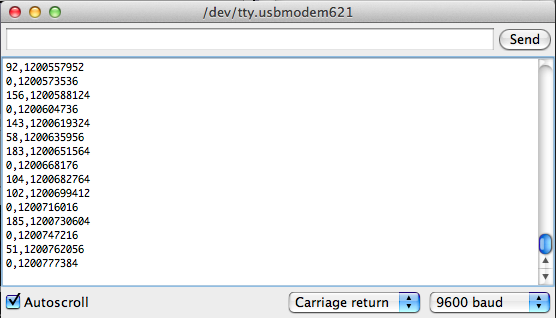
Take note of some of the higher values; you'll want to use these when setting thresholds for your event triggers.
Timing Events
Once everything has been connected and verified, we can start timing events. Create a stereo audio file with tones that start on the right and left channels at different times. Example
Now configure the Arduino timer to watch for the audio events. This is done by sending configuration commands over the serial connection. There are 3 main setup commands: 'ARM', 'START', and 'STOP'.
Each of these takes three parameters:
- 'A' or 'D' (specify if the input pin is analog or digital)
- 0 - 12 (the pin number)
- 0 - 1024 (the threshold value to look for)
'START' is used to specify which pin and what threshold to use to start the timer. Similarly, 'STOP' is used to specify which pin and what threshold to use to stop the timer.
A third, optional configuration command, 'ARM', takes the same 3 parameters as 'START' and 'STOP' and can be used to synchronize the timer with an external system. If 'ARM' is supplied, any 'START' and 'STOP' events will be ignored until after the 'ARM' event happens. Think of this as a clapperboard / film slate for your experiment. For timing the onset of two signals from a stereo audio source, we won't need to use the 'ARM' command.
For this example, the channel that plays sound first is plugged in to pin A0 and the channel that plays sound second is plugged in to pin A1. The threshold is set very low. ::
  START A 0 5
  STOP A 1 5
Once all of the configuration commands have been set, we can start the timer with the 'RUN' command::
RUN
If you've configured this over a serial monitor connection, you should see something like this:
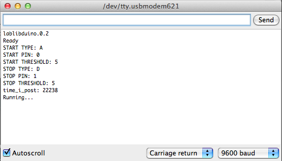
Now the timer is waiting for our first trigger, 'START'. If all goes well, we should be able to trigger our 'START' and 'STOP' by playing the sound. Try it out!
If all went well you should see something like this:

The results show the time in milliseconds when each of the triggers were met. We can find the difference in onset to onset of our start and stop sources by subtracting the started time from the stopped time. In this case, 26308 - 25036 = 1272.
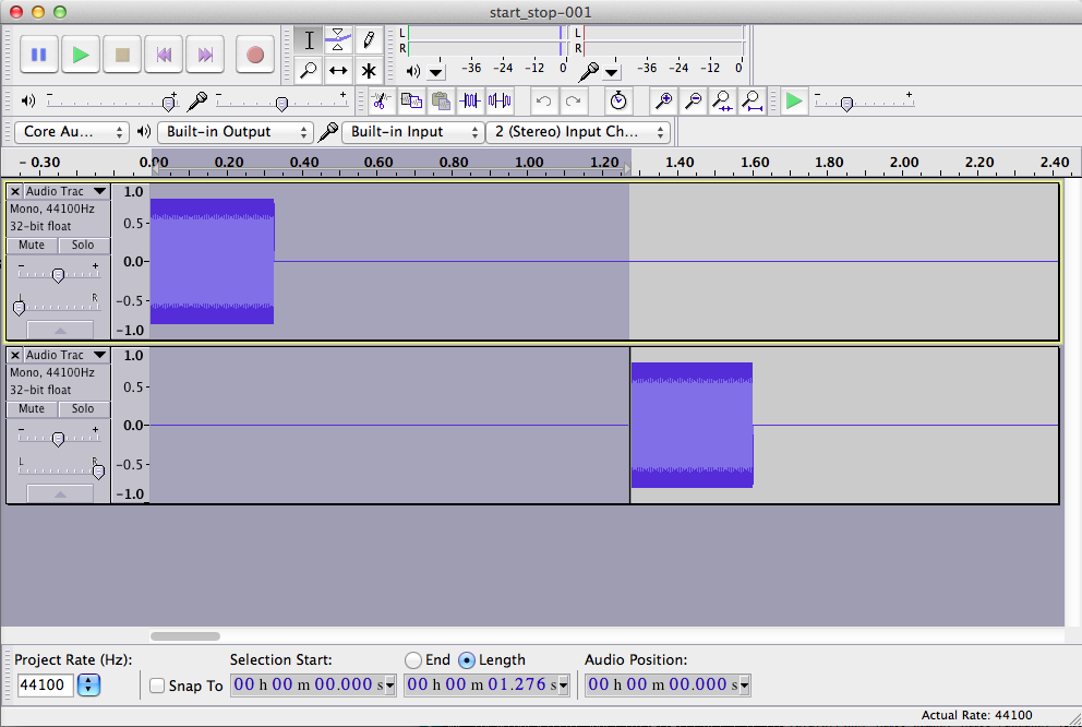
This is 4ms short of the measured time in audacity.
Calibration
Short Version
The 4ms difference noted above may be adequate for some situations, but after some simple calibration, we can do even better.
In order to improve the accuracy of the Arduino as a timer, it is important to measure the actual clock speed of your particular Arduino. The actual clock speed does vary from one board to the next (especially from one type of board to the next). This variation makes a difference in the times measured. Fortunately, if you've followed this setup, you now have everything you need to measure the actual clock speed.
Run the included "generate_play_collect.py" script to run some tests. It will make wave files with a random amount of silence separating the two tones, set up your Arduino for measurements, and then log the results from the timing. You may want to adjust the number of trials run in the script. (The number of tests is currently set to 10 in the run_many() function.)
After the tests have been run, you can find the ratio of the frequency mismatch by running "compare_times.py".
Finally, find the variable "clock_adjust" in the "src/sketch.ino" file and update it with the value given from compare_times.py. After you build and upload the sketch to your Arduino, the results will be adjusted by that ratio. These results should be much closer (+/- 500 microseconds) to the actual time measured in the audio file.
A Little More Detail
The clock frequency for Arduino microcontrollers is approximated for different types of Arduino devices. Although this estimate is good enough for many timing based applications, it is not ideal when trying to use the Arduino to measure timing of events more accurately. To improve this accuracy, it is possible to measure the clock frequency of a specific Arduino for use as a better approximation in sketches. Here we outline one simple approach for making this measurement.
Deep in the heart of the Arduino software is a setting that defines the expected clock frequency for a given board. (The variable is called F_CPU and in my case it is found in a file called boards.txt. YMMV.) For many Arduino boards, this is set to a default value of "16000000L", or 16MHz.
However, not all Arduino microcontrollers are the same. Some use crystal oscillators for the clock, while others use ceramic resonators. These each have their own pros and cons with regard to the stability of the clock. They are similar in that neither are likely to match the default value of 16MHz exactly. Some may be faster than the specified default, some may be slower.
For many timing sensitive applications, like serial communication, there is a built in tolerance for this variation. As long as the times are close enough, everything still works as expected.
When using the Arduino as a clock to measure events over longer periods of time (say, a few seconds or more), the mismatch in frequency shows up as drift in the measured values. If the actual clock value is faster than the default specified, more cycles will be counted than the number expected to happen within the time. This results in reported times that are longer than they should be. Inversely, if the actual clock value is slower than the default, fewer cycles will be counted than the number expected for the time. Measured times will be reported as shorter than they should be. Over longer periods of time, this discrepancy will get more and more noticeable.
This frequency mismatch is one of the largest sources of timing errors for the Arduino. Fortunately it is easy to measure and correct for.
For details about other sources of errors in the times reported by an Arduino, and an alternative approach for measuring these errors, please see here:
http://jorisvr.nl/arduino_frequency.html
Measuring the Discrepancy
To make measurements, we use an audio source signal whose measurements are already known and play and measure it as before. By playing that source signal and then comparing the results measured by the Arduino, we'll start to get an idea of how much the measurements from the Arduino are off by.
This process is automated by the included generate_play_collect.py script. This script will generate an audio file where the tone on one channel starts playing immediately. This is the tone that will trigger the START event. The other channel does not start until after a random (but measured) amount of time. This triggers the STOP event. The generated file is played three times, and the results are collected after each play. At the end of those three plays, the results are logged to a CSV file and the process is repeated. You can configure the number of times it repeats by editing the script.
Adjusting Results
After generate_play_collect completes, the results can be processed with compare_times.py. This script will look at the previously created output and average all of the differences. At the end it will print:
frequency mismatch (clock_adjust):
Take that value and change the corresponding 'clock_adjust' variable in the main sketch.ino file. After saving this change, you will need to re-build and re-upload the sketch to your Arduino. Now, if you run the test again, the reported times should be much more accurate (+/- 500 micro seconds).